

Computed Tomography
Computed Tomography or more commonly just CT is rapidly gaining acceptance as a non-destructive testing (NDT) method for the inspection of parts in the automotive, aerospace, casting and electronics industries to name but a few, each with its own set of challenges. Inspecting the parts with CT opens up potential new applications, such as evaluating internal defects and the dimensional measurement of internal structures.
What is CT and how does it help me?
It is well known that traditional X-ray technology makes hidden detail visible.
CT is a technology that uses computer-processed X-rays to produce tomographic images (virtual ‘slices’) of specific areas of the scanned object, allowing the user to see what is inside it without cutting it open. In its simplistic form, it’s rather like taking a loaf of bread, slicing it with CT, and then being able to inspect each slice for features without having physical to cut it. Digital geometry processing is then used to generate a three-dimensional image of the inside of an object from a large series of two-dimensional radiographic images taken around a single axis of rotation. Medical imaging is still the most common application of X-ray CT, but it is now becoming increasingly prevalent in NDT.
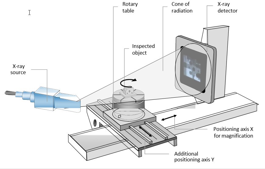
A typical CT set-up is shown below.
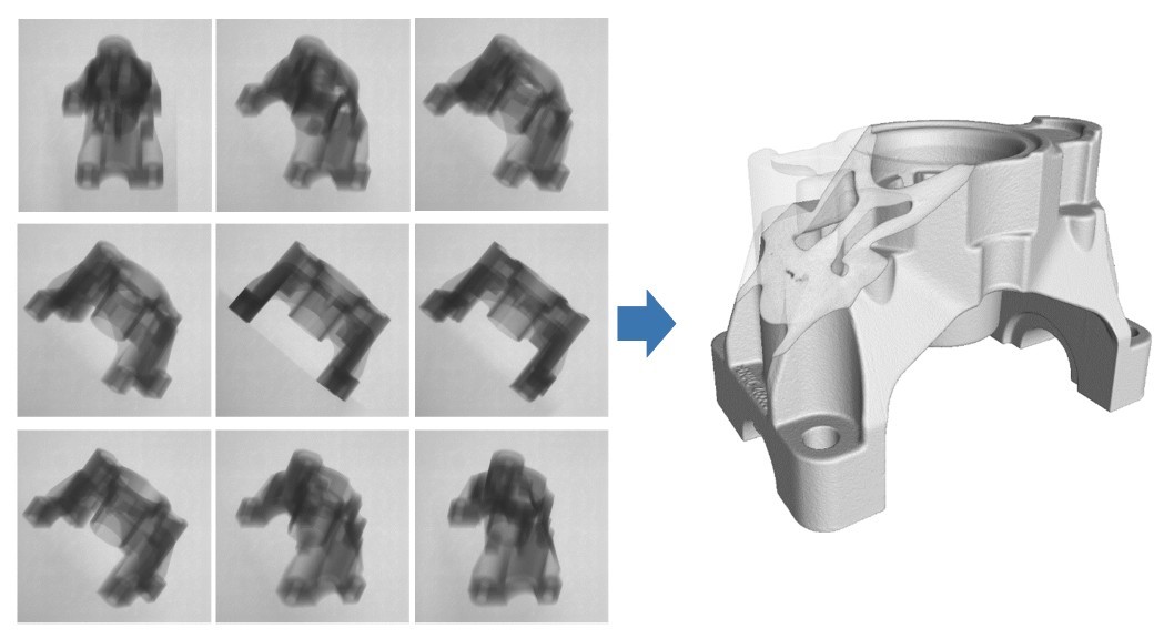
Reconstruction is carried out from using the projection sets to create a 3D volume data as shown below.
CT can therefore help you by:
3D Inspection – Precisely locate and measure defects. Knowing where a defect is located in an Aluminium casting, may turn it from a scrap part to an acceptable part, as the defect may be removed by a subsequent machining operation.
Metrology – Depending on the resolution of the CT system, checking the dimensional accuracy of internal features, target/actual comparison with a CAD model or wall thickness analysis can be achieved.
CT Systems:
Euroteck Systems have represented Bosello, now a ZEISS company for more than 15 years.
ZEISS is an international leading technology enterprise operating in the fields of optics and optoelectronics. The ZEISS group is divided into four operational divisions comprising Quality & Research, Medical Technology, Consumer Markets and Semiconductor Manufacturing Technology and is represented in more than 40 countries and has over 50 sales and service locations and more than 30 manufacturing sites around the world.
ZEISS UK – Industrial Metrology is located in Rugby, close to our Tamworth facility and have a customer demonstration area comprising CT, CMM and Microscopy systems.
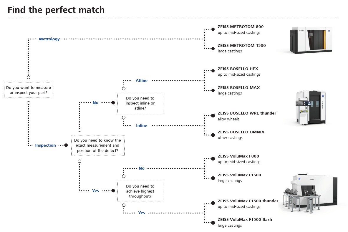
The table below gives a brief overview of the ZEISS CT systems:
Zeiss VoluMax F1500 Thunder
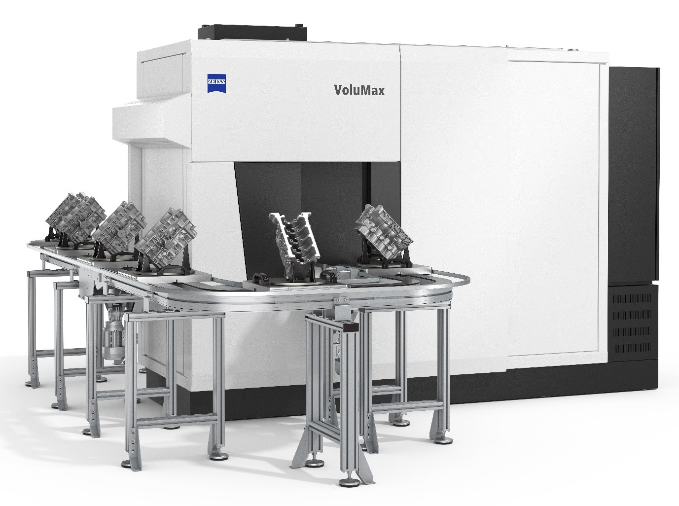
Like all CTs in the ZEISS VoluMax family, the system is characterised by its robustness, which guarantees reliable quality assurance in production environments. In order to achieve the greatest possible efficiency in production, the compact CT can be flexibly integrated in the smallest space according to the individual requirements of the respective production line. The system is also – and this is unique on the market – equipped with an automatic conveyor loading system that feeds the parts directly through the CT. With only eight seconds per part for loading and unloading, downtimes are reduced to a minimum. The actual scan time could be as low as 36 seconds, depending on the part.
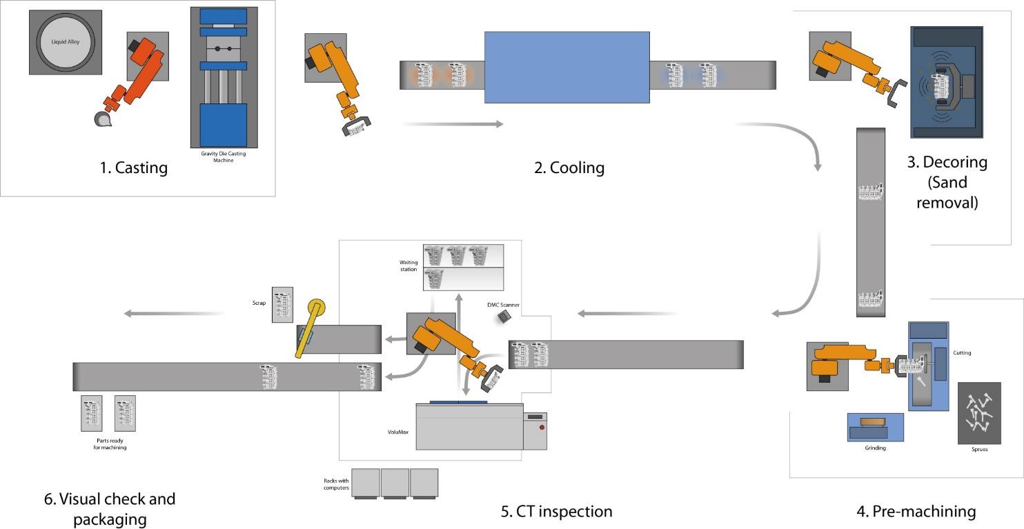
A typical in-line automated workflow schematic is shown below:
Automatic Defect Recognition:
The ZEISS Automated Defect Detection (ZADD) evaluation software is particularly valuable for users. Not only does ZADD detect such defects as cavities, cracks or pores, it also classifies and locates them. However, the greatest advantage for the user lies in the evaluation of the defects: the software indicates whether a detected defect will cause problems during later production steps. For an example an unacceptable defect may be located in the machining band. The software while recognizing it as unacceptable will not reject the part because the defect will be removed by a subsequent machining operation, thus saving unnecessary scrap. It also enables manufacturers to sort out defective parts reliably and precisely. If individual defects occur frequently, customers can intervene in the production process earlier and avoid increased rejects.
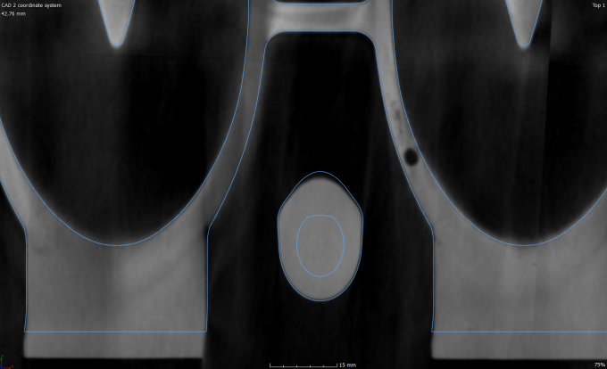
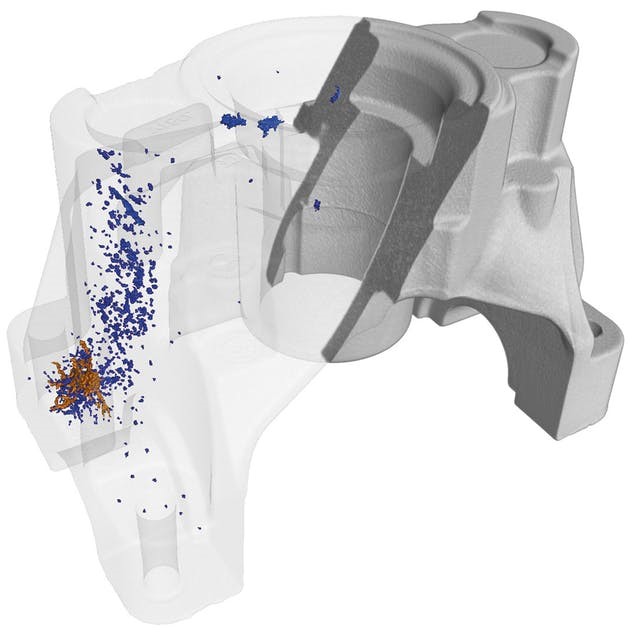
CT image of Aluminium cylinder head shown above. Machining allowance shown as blue line. Defect falls inside machining allowance so will not be exposed subsequently. Depending on acceptance criteria, this casting is potentially acceptable.
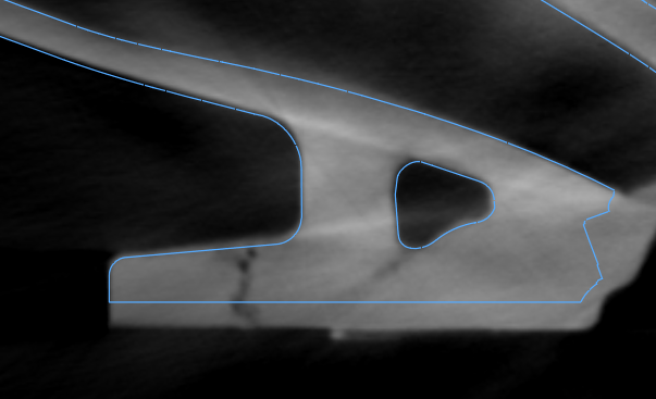
The defect shown circled in red would become a surface breaking defect after the machining operation. Whilst the defect might be acceptable in the raw condition, after machining, the casting would be scrap. In-line CT thus saving the added costs of machining a scrap part.
A coherent package: hardware, software and service
The ZEISS VoluMax F1500 Thunder comes with software. This fits seamlessly into the entire production and quality assurance process.
The ZEISS VoluMax F1500 Thunder requires very little maintenance. If problems should arise, the simple configuration of the system allows users to correct minor errors themselves. If necessary, Euroteck service engineers are also available – with technicians on site and all spare parts on stock. This means that production can be restarted quickly.
Please do not hesitate to contact Euroteck Systems to discuss your Computed Tomography requirement.